ECE :: Analog Electronics
-
A full wave rectifier circuit using centre tapped transformer and a bridge rectifier are fed at 100 V, 50 Hz. The frequencies of outputs in these two rectifiers are
-
When the ac base voltage in a CE amplifier circuit is too high, the ac emitter current is
-
When load is coupled to class A amplifier through transformer, efficiency decreases.
-
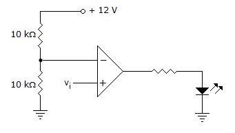
In the circuit figure LED will be on when v1 is
-
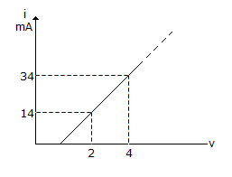
Figure shows a portion of linear v - i characteristics of diode. If applied voltage is + 6 V, the current will be
-
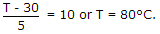
A power transistor dissipates 5 W. If ambient temperature is 30° and case to air thermal resistance is 10° C/W, the case temperature is
-
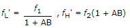
An R-C coupled amplifier has mid-frequency gain of 200 and a frequency response from 100 Hz to 20 kHz. A negative feedback network with β = 0.2 is incorporated into the amplifier circuit, the Bandwidth will be

 Whatsapp
 Facebook


 . Therefore, vi should be more than 6 V.
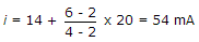 .
.