Home / ECE / Analog Electronics :: Section 3

ECE :: Analog Electronics

  1. In figure the zener current

  2. A.
    is always 130 mA
    B.
    may vary between 10 mA and 130 mA
    C.
    may vary between 60 mA and 130 mA
    D.
    is always equal to 65 mA

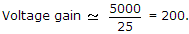
  3. In a commercially available good power supply the voltage regulation is about

  4. A.
    1%
    B.
    5%
    C.
    10%
    D.
    20%

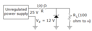
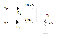
  5. In the circuit of figure the diode

  6. A.
    will conduct as the whole cycle
    B.
    will conduct in the positive half cycle
    C.
    will not conduct
    D.
    will conduct from 30° to 150° in the positive half cycle

  7. The most commonly used bias in BJT amplifier circuits is

  8. A.
    voltage divider bias
    B.
    emitter bias
    C.
    collector bias
    D.
    collector feedback bias

  9. In the circuit of figure, v1 = v2 = 10 V. Then

  10. A.
    I1 = I2
    B.
    I1 > I2
    C.
    I2 > I1
    D.
    I1 = 0

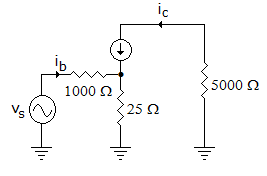
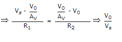
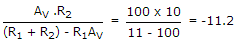
  11. The inverting op-amp shown in the figure has an open loop gain to 100. The closed loop given is

  12. A.
    -8
    B.
    -9
    C.
    -10
    D.
    -11

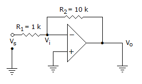
  13. In a voltage regulated power supply the zener operates in the breakdown region when (Vin is input voltage and Vz is zener breakdown voltage)

  14. A.
    Vin < Vz
    B.
    Vin > Vz
    C.
    Vin = Vz
    D.
    both (a) or (b)

  15. The parameter h11 for CB circuit is higher than that for CE circuit.

  16. A.
    True
    B.
    False

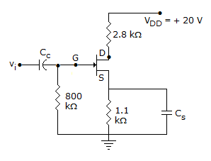
  17. Figure shows a self bias circuit for FET amplifier, ID = 4 mA. Then IS =

  18. A.
    4 mA
    B.
    2 mA
    C.
    0.4 mA
    D.
    0.2 mA

  19. In the CE equivalent circuit of figure, the voltage gain is

  20. A.
    200
    B.
    40
    C.
    5
    D.
    1000