ECE :: Analog Electronics
-
When the circuit is switched on, the loop gain of a Wien bridge oscillator is
-
The op-amp circuit shown in the figure is a filter. The type of filter and its cut off type of filter and its cut off frequency are respectively.

-
A 741 type op-amp has a gain bandwidth product of 1 MHz. A non-inverting amplifier using this op-amp and having a voltage gain of 20 dB will exhibit a -3dB bandwidth of
-
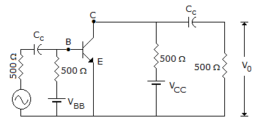
In a full wave rectifier circuit using centre tapped transformer, the peak voltage across half the secondary winding is 40 V. If diodes are ideal, the average output voltage is


 Whatsapp
 Facebook


 .
. .
.

 106 = β x A
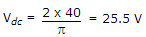 .
.