ECE :: Analog Electronics
-
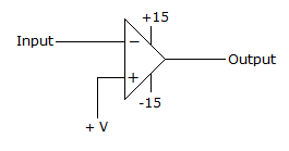
Assertion (A): The circuit in figure produces repetitive narrow pulses when input is fed with sine or triangular waveform having peak value more than + V
Reason (R): The high gain op-amp produces voltages at two levels. If input is more than + V, the output is + 15 V otherwise the output is - 15 V.
-
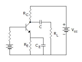
In a CE amplifier drives a low load resistance directly the result will be
-
For high frequencies a capacitor like
-
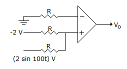
A non-inverting op-amp summer is shown in figure, the output voltage V0 is
-
In following figure find VGG by assuming gate current is negligible for the p-channel JFET. (if IDQ = - 6 mA, RS = 0, VDD = -18 V, RD = 2 kΩ, IDSS = - 10 mA, IPO = - 3 V)
-
A difference amplifier using op-amp has closed loop gain = 50. If input is 2 V to each of inverting and non-inverting terminals, output is 5 mA. Then CMRR =
-
The coupling capacitor in amplifier circuits


 Whatsapp
 Facebook




 .
. . If w is very high, XC, is nearly zero.


 sin ωt
 .
.
 .
. .
.