ECE :: Network Analysis and Synthesis
-
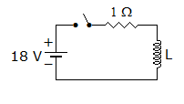
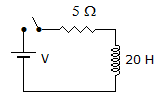
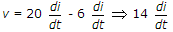
In figure, the switch is closed at t = 0 when current through inductor is 6 A, the rate of change of current through resistor is 6 A/s. The value of L is
-
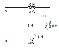
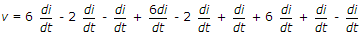
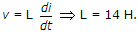
In figure, the switch is closed at t = 0. At t = 0+, di/dt = 4 A/s. Then V =
-
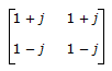
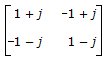
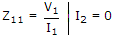
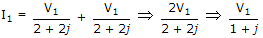
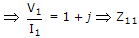
For the lattice circuit shown in the figure Za = j2 Ω and Zb = 2 Ω. The values of the open circuit impedance parameters Z =
 are
are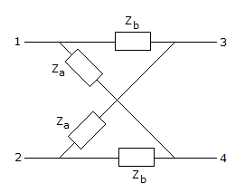
-
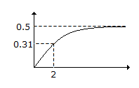
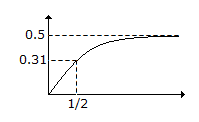
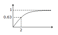
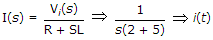
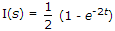
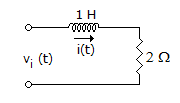
For the R-L circuit shown in the figure, the input voltage vi(t) = U(t). The current i(t) is
-
If f(t) = - f(- t) and f(t) satisfies Dirichlet conditions, then f(t) can be expanded in Fourier series having
-
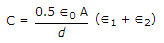
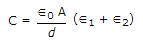
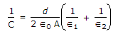
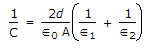
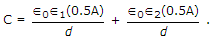
A parallel plate capacitor has plate area A and distance between the plates is d. It has two dielectrics each of thickness d and area 0.5 A. The dielectric constants are ∈1 and ∈2. The total capacitance is given by the equation
-
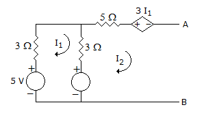
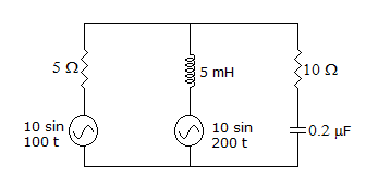
Which of the following theorems can be conveniently used to find power consumed in 10 Ω resistor in figure?
-
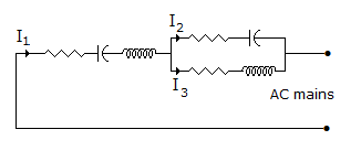
In the circuit of figure is

 Whatsapp
 Facebook


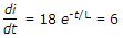 . Therefore, L = 2H.


 .
.