Home / ECE / Network Analysis and Synthesis :: Section 27

ECE :: Network Analysis and Synthesis

  1. A capacitor is considered to be completely charged in __________ time constant.

  2. A.
    one
    B.
    three
    C.
    five
    D.
    eight

  3. For an m-derived high pass filter

  4. A.
    True
    B.
    False

  5. Consider the following statements associated with two port networks.

    1. Z12 = Z21
    2. Y12 = Y21
    3. h12 = h21
    4. AD - BC = 1
    Which one of the statement given above are correct?

  6. A.
    1, 2, 3
    B.
    2, 3, 4
    C.
    1, 3, 4
    D.
    1, 2, 4

  7. Assertion (A): The number of basic loops is equal to number of links.

    Reason (R): The graph theory helps in choosing independent variables in circuit analysis.

  8. A.
    Both A and R are true and R is correct explanation of A
    B.
    Both A and R are true and R is not the correct explanation of A
    C.
    A is true but R is false
    D.
    A is false but R is true

  9. In an R-L-C circuit, v(t) = 20 sin (314 t + 5 p/6) and i(t) = 10 sin (314 t + 2p/3). The p.f of the circuit is

  10. A.
    0.5 lead
    B.
    0.866 lag
    C.
    0.866 lead
    D.
    0.5 lead

  11. In any network of linear impedances the current flowing at any point equal to algebric sum of currents caused to flow at that point by each of the emf taken separately with all other emfs reduced to zero. The statement represents.

  12. A.
    KCL
    B.
    Norton's theorem
    C.
    Thevenin's theorem
    D.
    Superposition theorem

  13. The Kirchoff's laws fail in which of the following circuits?

  14. A.
    Linear circuits
    B.
    Non-linear circuits
    C.
    Lumped parameters circuits
    D.
    Distributed parameters circuits

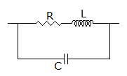
  15. A black box has one of the elements our of R, L, C. when a 220 V a supply is connected the current supplied by source is I. when a 0.1 F capacitor is connected in parallel with the box, the current is 2I. The element is

  16. A.
    resistance
    B.
    inductance
    C.
    0.1 F capacitance
    D.
    not identifiable on the basis of given data

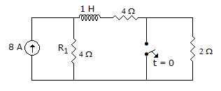
  17. In figure, the switch has been in closed position for a long time. At t = 0, the switch is opened. At t = 0+, the current R1 is

  18. A.
    8 A
    B.
    4 A
    C.
    6 A
    D.
    2 A

  19. The expression for the resonant frequency ω0 in the circuit shown

  20. A.
    1/LC
    B.
    C.
    D.
    none