ECE :: Automatic Control Systems
-
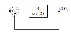
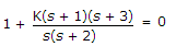
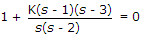
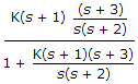
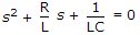
For the system in the given figure the characteristic equation is
-
Mechanical impedance is the ratio of
-
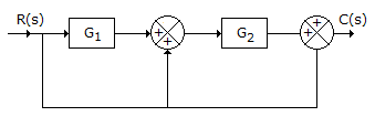
For the system in the given figure. The transfer function C(s)/R(s) is
-
Whether a linear system is stable or unstable that it
-
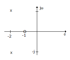
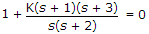
In the given figure shows pole-zero plot. If steady state gain is 2 the transfer function G(s) is
-
If a system is to follow arbitrary inputs accurately the bandwidth should be
-
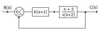
For the system of the given figure, the damping ratio of closed loop poles is
-
Assertion (A): Potentiometers can not be used as error detectors in position control systems.
Reason (R): The resolution of a potentiometer places an upper limit on its accuracy
-
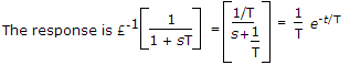
For a first order system having transfer function
 , the unit impulse response is

 Whatsapp
 Facebook


 .
.  .
. , force/velocity = mechanical impedance.
 =
=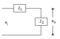


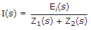 , E0(s) = [I(s)][Z2(s)] or
  .
.


 .
.  .
.