Home / ECE / Analog Electronics :: Section 7

ECE :: Analog Electronics

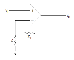
  1. When Z1 << Z, The circuit of figure works as

  2. A.
    inverting amplifier
    B.
    Schmitt trigger
    C.
    non-inverting amplifier
    D.
    source follower

  3. In a class C operation VCC = 40 V, RL = 50 Ω. The maximum load power can be

  4. A.
    64 W
    B.
    32 W
    C.
    16 W
    D.
    8 W

  5. IF VCC = 15 V, VCEQ = 5 V and ICQ = 50 mA, the efficiency in class A operation is

  6. A.
    100%
    B.
    50%
    C.
    25%
    D.
    16.7%

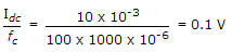
  7. A bridge rectifier circuit has a dc load current of 10 mA and a filter capacitance of 1000 μF. The peak to peak ripple voltage is

  8. A.
    0.01 V
    B.
    0.05 V
    C.
    0.1 V
    D.
    0.5 V

  9. Which of the following best represents the bandwidth of an actual op-amp?

  10. A.
    100 Hz to 1 MHz
    B.
    0 Hz to 100 kHz
    C.
    0 Hz to 10 MHz
    D.
    0 Hz to infinity

  11. For an ideal noise free transistor amplifier the noise factor is

  12. A.
    zero
    B.
    zero dB
    C.
    1 dB
    D.
    depends on other factors

  13. In a crystal

  14. A.
    the frequencies of series and parallel resonance are equal
    B.
    the frequency of series resonance is more than frequency of parallel resonance
    C.
    the frequency of parallel resonance is more than frequency of series resonance
    D.
    None of the above

  15. Ultra high frequency oscillators work in the range

  16. A.
    20 Hz to 20 kHz
    B.
    1 kHz to 30 kHz
    C.
    30 kHz to 30 MHz
    D.
    above 30 MHz

  17. N-channel FETs are superior to p-channel FETs because

  18. A.
    mobility of electrons is smaller than that of holes
    B.
    mobility of electrons is greater than that of holes
    C.
    they consume less power
    D.
    they have high switching time

  19. In the circuit of figure, v0 =

  20. A.
    3 v1 + 4 v2
    B.
    -3 v1 - 4 v2
    C.
    4 v1 + 3 v2
    D.
    -4 v1 - 3 v2