Home / ECE / Network Analysis and Synthesis :: Section 17

ECE :: Network Analysis and Synthesis

  1. At very low frequencies a series R-C circuit behaves as almost purely __________ .

  2. A.
    resistive
    B.
    inductive
    C.
    capacitive
    D.
    none of the above

  3. In a composite filter terminating half sections are used for impedance matching.

  4. A.
    True
    B.
    False

  5. The bridge is balanced when the value of R is

  6. A.
    50 Ω
    B.
    100 Ω
    C.
    200 Ω
    D.
    250 Ω

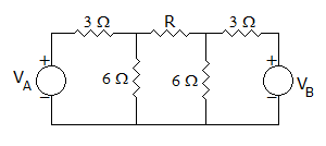
  7. In figure, the current through R is 1 A when VA = 0 and VB = 15V. If both VA and VB are increased by 15V each, current through R will be
  8. A.
    1 A
    B.
    0.5 A
    C.
    3 A
    D.
    0.33 A

  9. When a series RL circuit having power factor angle 0 is switched on to an ac voltage Vm sin (ωt + Φ), the transient term is zero if Φ = 0.

  10. A.
    True
    B.
    False

  11. A series resonant circuit is capacitive at f = 150 Hz. The circuit will be inductive somewhere at

  12. A.
    f greater than 150 Hz
    B.
    f less than 150 Hz
    C.
    f equal to 150 Hz by increasing the value of the resistance
    D.
    none of the above

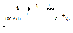
  13. In the circuit of figure, the switch is closed at t = 0 with iL (0) = 0 and VC (0) = 0. In the steady state nc equals.
  14. A.
    100 v
    B.
    0 v
    C.
    D.
    - 100 v

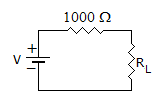
  15. The maximum power that can be transferred to the load is resistor RL from the voltage source in the figure is
  16. A.
    1 W
    B.
    10 W
    C.
    0.25 W
    D.
    0.5 W

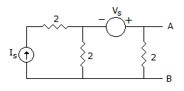
  17. The Thevenin equivalent circuit to the left of AB has Req

  18. A.
    2 Ω
    B.
    4 Ω
    C.
    1 Ω
    D.
    3 Ω

  19. A current increasing at the rate of 1A/s is passed through a 1 H inductor. At t = 0, i = 0. The flux linkages after 1 sec are

  20. A.
    0.5 Wb-turn
    B.
    1 Wb-turn
    C.
    2 Wb-turn
    D.
    4 Wb-turn