Home / ECE / Network Analysis and Synthesis :: Section 17

ECE :: Network Analysis and Synthesis

  1. Poor power factor

  2. A.
    reduces load handling capability of electrical system
    B.
    results in more power losses in the electrical system
    C.
    overloads alternators, transformers and distribution lines
    D.
    all

  3. The input resistance of the network in figure is

  4. A.
    1.5 R
    B.
    C.
    D.

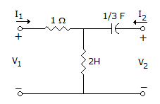
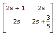
  5. If two networks are cascaded then

  6. A.
    [y] = [ya] . [yb]
    B.
    [Z] = [Za] . [Zb]
    C.
    [aa] = [bb]
    D.
    [aa] + [bb]

  7. When a series RL circuit is switched on to a dc voltage, the rate of change of current is maximum at t = 0.

  8. A.
    True
    B.
    False

  9. In the set of equation

    x1 =


  10. Z-matrix for the network shown in the given figure is


  11. In a circuit containing a complex impedance, maximum power transfer takes place when load is

  12. A.
    pure resistance
    B.
    equal to the complex impedance
    C.
    conjugate complex of the circuit impedance
    D.
    none of the above

  13. The resistance of a bulb at the time of full brightness is 1200 Ω. Then the resistance at room temperature is about

  14. A.
    1200 Ω
    B.
    120 Ω
    C.
    600 Ω
    D.
    10 Ω

  15. For a delayed half wave rectified wave, the average and rms values are lower than those for half wave.

  16. A.
    True
    B.
    False

  17. A reactance function is always a quotient of

  18. A.
    even to odd polynomials
    B.
    odd to even polynomials
    C.
    even to odd or odd to even polynomials
    D.
    even to even polynomials