ECE :: Network Analysis and Synthesis
-
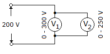
In figure readings of the two voltmeters should be
-
The internal impedance of a source is 3 + j 7 Ω. For maximum power transfer, load impedance should be
-
In the circuit of figure, the current through battery E3 is

-
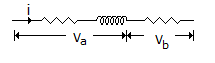
In the circuit of figure
-
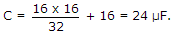
Two capacitors of 16 μF each are connected in series. Another capacitor of 16 μF is connected in parallel with this combination. The total capacitance will be
-
Assertion (A): Operator has a value 1 ∠ - 90° or 1 ∠ 90°.
Reason (R): Operator 'a' has a value 1 ∠ 120°.
-
The maximum current and voltage ratings for a 0.5 W, 10 kW resistor are
-
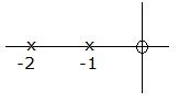
Figure shows a pole zero plot of I(s). The likely current response in time domain is
-
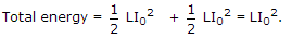
In a series RLC circuit, the current at resonance is I0 the total energy stored in the circuit at resonance is

 Whatsapp
 Facebook


 .
.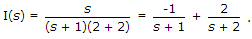 Therefore , i(t) = -e-t + 2e-2t
 The dc gain is