ECE :: Network Analysis and Synthesis
-
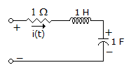
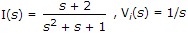
The circuit shown in the figure has initial current iL(0) = 1A through the inductor and an initial voltage vc(0) = 1 V across the capacitor. For input v(t) = U(t) the Laplace transform of the current i(t) for t ≥ 0 is
-
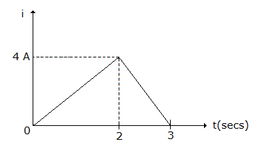
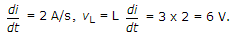
The current wave of figure, is passed through a 3 H inductor during the period 0 to 2 seconds
-
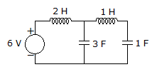
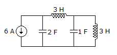
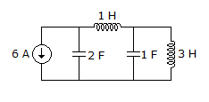
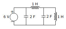
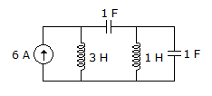
The minimum number of equations required to analyze the circuit shown in the figure is
-
If Z(s) has a pole at origin, the realization leads to
-
A series resonant circuit has inductance L. If L is increased, the resonant frequency
-
In a coupled coil the primary has 100 turns and secondary has 200 turns. The primary produces, a flux Φ = e-t. The coefficient of coupling is 1. The voltages induced in secondary is


 Whatsapp
 Facebook


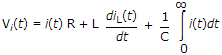
 Vi(s) = I(s).R + Ls I(s) - Li(0+) +
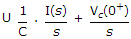
 .
.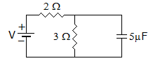
 . Hence RC = 6 μs.
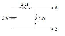
 . Hence, the network has capacitance in series.
 . As L increases ωr decreases.


 .
.