ECE :: Network Analysis and Synthesis
-
If
 , the network has
 -
The total inductance of two coils is 60 mH in series aiding connection and 40 mH in series opposing connection. The mutual inductance between coils is
-
The transfer function
 of an R-L-C circuit given by
 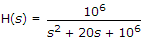 The Quality factor (Q-factor) of this circuit is
 -
An RC circuit initially at rest has a step signal. The response V(t) across C is V(t) = 1 - e-at, If now there is an initial voltage on C of 2 volts for the same step signal, V(t) is now
-
In the network of the figure is the maximum power is delivered to RL if its value is

-
A two-port network is represented by ABCD parameters given by

If port is terminated by RL, then input impedance seen at port 1 is given by -
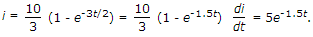
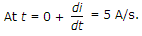
A series circuit having R = 3 Ω and L = 2 H is excited by a 10 V battery. At t = 0+, di/dt is
-
Three resistances of 15 Ω, 10 Ω and 3 Ω are connected in parallel. The overall resistance is
-
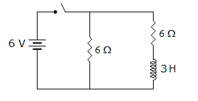
In figure, the switch is closed at t = 0. At t = 0+ The value of current supplied by battery is

 Whatsapp
 Facebook


 which means 1 H inductance and 1 F capacitor in parallel.


 .
.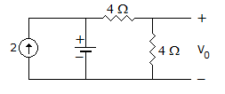
 Vf = 4 x 2 = 8 volt.
 .
.


 .
.