ECE :: Network Analysis and Synthesis
-
Two sinusoidal voltage sources v1 = 50 sin (100t) and v1 = 50 sin (100t + p) are connected in parallel and fed an inductance XL = 2Ω. The cuirent through XL is
-
A system function
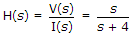 , the system is at rest for t < 0. For i(t) = u(t), then v(t) is given by
 -
Two voltages 50 V each have a phase difference of 45°. The rms value of resultant sum of the two voltages is
-
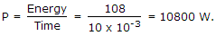
The energy stored in a coil is 108 J. It is opened suddenly in 10 ms. The power dissipated instantaneously across the blades of switch is
-
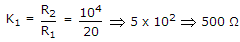
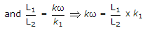
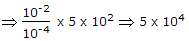
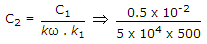
A parallel RLC circuit with R1 = 20,
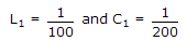 is scaled giving R2 = 104, L2 = 10-4 and C2, the value of C2 is
 -
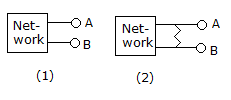
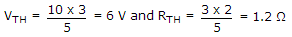
The Thevenin's equivalent of network in figure(1) is a 10 V source in series with 2 Ω resistance. If a 3 Ω resistance is connected across AB as shown in figure(2) the Thevenin's equivalent is

 Whatsapp
 Facebook


 .
.
 0.02 x 10⁻⁸
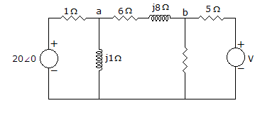
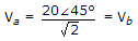 . Since equal resistances of 5Ω are on two sides of node b,
 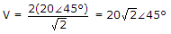 .
. .
.