Home / ECE / Digital Electronics :: Section 19

ECE :: Digital Electronics

  1. The counter shown in the given figure is

  2. A.
    Synchronous
    B.
    Johnson
    C.
    Ring
    D.
    None of the above

  3. The number of bits in a nibble is

  4. A.
    8
    B.
    4
    C.
    2
    D.
    16

  5. In digital computer programming, subroutines are used

  6. A.
    to reduce program execution time at the expense of more memory
    B.
    to reduce storage requirements
    C.
    to increase programming ease and reduce storage requirements
    D.
    because most of the functions are same

  7. Equation xl0 = 110010012 when solved for x gives the value of x as

  8. A.
    8
    B.
    111
    C.
    152
    D.
    201

  9. Nibble is

  10. A.
    a string of 4 bits
    B.
    a string of 8 bits
    C.
    a string of 16 bit
    D.
    a string of 64 bits

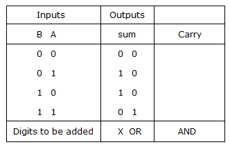
  11. The sum S of A and B in a Half Adder can be implemented by using K NAND gates. The value of K is

  12. A.
    3
    B.
    4
    C.
    5
    D.
    none of these

  13. When a bit is 0 is a DDR, it makes the corresponding port pin an __________ On the other hand, a 1 bit programs a __________ Pin.

  14. A.
    output, input
    B.
    output, output
    C.
    input, input
    D.
    input, output

  15. Which of the following input is not possible in case of a SR flip-flop?

  16. A.
    S = 0, R = 0
    B.
    S = 0, R = 1
    C.
    S = 1, R = 0
    D.
    S = 1, R = 1

  17. The Truth Table shown is for a

  18. A.
    CMO
    B.
    counter
    C.
    flip-flop
    D.
    half adder

  19. The advantages of flash memory over EEPROM are

  20. A.
    higher density
    B.
    lower cost
    C.
    both higher density and lower cost
    D.
    none of the above