Home / ECE / Automatic Control Systems :: Section 8

ECE :: Automatic Control Systems

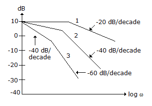
  1. The given figure shows dB magnitude plots for type 0, type 1 and type 2 systems. Out of these

  2. A.
    curves 1, 2, 3 are for type 0, 1, 2 systems respectively
    B.
    curves 1, 2, 3 are for type 2, 1, 0 systems respectively
    C.
    curves 1, 2, 3 are for type 1, 0, 2 systems respectively
    D.
    curves 1, 2, 3 are for type 1, 2, 0 systems respectively

  3. Assertion (A): A. For a unity feedback system, with 
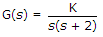
, the settling time of step response is constant for all values of K ≥ 1

    Reason (R): The real part of the roots for all values of K ≥ 1 are negative.

  4. A.
    Both A and R are correct and R is correct explanation of A
    B.
    Both A and R are correct but R is not correct explanation of A
    C.
    A is correct but R is wrong
    D.
    R is correct but A is wrong

  5. Assertion (A): F(s) is valid throughout s plane except at poles of F(s).

    Reason (R): £[f1(t) + f2(t)] = £[f1(t)] + £[f2(t)]

  6. A.
    Both A and R are correct and R is correct explanation of A
    B.
    Both A and R are correct but R is not correct explanation of A
    C.
    A is correct but R is wrong
    D.
    R is correct but A is wrong

  7. For the given figure, the transfer function X(s)/P(s) =


  8. In the given figure shows a root locus plot. Consider the following statements for this plot

    1. The open loop system is a second order system
    2. The system is overdamped for K > 1
    3. The system is stable for all values of K
    Which of the above statements are correct?

  9. A.
    1, 2, 3
    B.
    1, 3
    C.
    2, 3
    D.
    1, 2

  10. In terms of ξ and ωn the settling time (5% criterion) of a second order system for a step input, is equal to


  11. The poles of an RC function

  12. A.
    are simple and lie on jω axis
    B.
    are simple and lie on negative real axis
    C.
    may be complex conjugate
    D.
    may be anywhere in s plane