ECE :: Automatic Control Systems
-
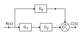
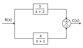
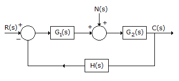
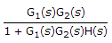
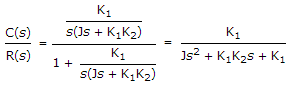
For the system in the given figure, the transfer function C(s)/R(s) is
-
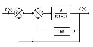
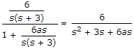
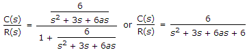
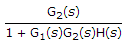
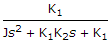
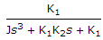
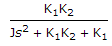
For the system in the given figure, the characteristic equation is
-
In control systems the magnitude of error voltage
-
The slope of log-magnitude asymptote changes by - 40 dB/ decade at a frequency ω1. This means that
-
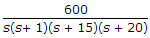
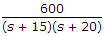
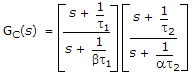
The transfer function
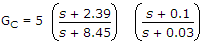 can be for
 -
The system of the given figure
-
If phase angle of open loop transfer function becomes - 180° at frequency ω1, then gain margin is equal to

 Whatsapp
 Facebook


 .
.  .
. 


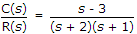 there are two poles at s = -2 and s = -1 and one zero at s = +3.
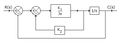
 .
.

 . In this case gain is |G(jω1)|.