Home / ECE / Network Analysis and Synthesis :: Section 23

ECE :: Network Analysis and Synthesis

  1. Which of the following theorems enables a number of voltage (or current) sources to be combined directly into a single voltage (or current) source?

  2. A.
    Superposition theorem
    B.
    Compensation theorem
    C.
    Millman's theorem
    D.
    Thevenin's theorem

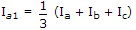
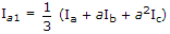
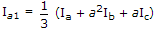
  3. If Ia, Ib, Ic are line currents and Ia1 is the positive sequences component of Ia then

  4. A.
    Ia1 = Ia + Ib + Ic
    B.
    C.
    D.

  5. If the numerator of Z(s) is one degree higher than denominator, Z(s) has a pole at infinity.

  6. A.
    True
    B.
    False

  7. An m derived low pass filter has fc = 1000 Hz, f = 1250 Hz and m = 0.6. If m is increased, then

  8. A.
    both fc and f will increase
    B.
    both fc and f will decrease
    C.
    fc will remain constant but f will decrease
    D.
    fc will remain constant but f will increase

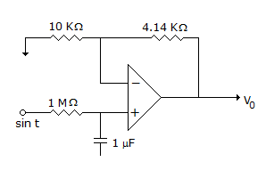
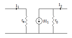
  9. In the two ports network shown in the figure, Z12 and Z21 are, respectively

  10. A.
    re and βr0
    B.
    0 and - βr0
    C.
    0 and βr0
    D.
    re and - βr0

  11. In figure, I = 2A, then V =

  12. A.
    5 V
    B.
    3 V
    C.
    2 V
    D.
    1 V

  13. The design of wave filter is based on characteristic impedance which is

  14. A.
    pure resistance
    B.
    pure reactance
    C.
    pure resistance in pass band and pure reactance in attenuation band
    D.
    pure reactance in pass band and pure resistance in attenuation band

  15. A system is said to be marginal stable if

  16. A.
    poles lies on Real axis
    B.
    zero lies on Real axis
    C.
    poles lies on Imaginary axis
    D.
    zeros lies on origin

  17. Assertion (A): In state space analysis, capacitors are taken to be in tree.

    Reason (R): State variable analysis is very suitable for computer solution.

  18. A.
    Both A and R are true and R is correct explanation of A
    B.
    Both A and R are true and R is not the correct explanation of A
    C.
    A is true but R is false
    D.
    A is false but R is true

  19. In the circuit shown in the given figure, V0 is given by

  20. A.
    B.
    C.
    sin t
    D.
    cos t