Home / ECE / Network Analysis and Synthesis :: Section 18

ECE :: Network Analysis and Synthesis

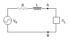
  1. For the network in figure, which of the following expressions gives the value of net inductance between terminals A and B
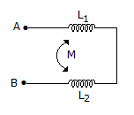
    1. L1 ± L2
    2. L1 ± L2 ± M
    3. L1 ± L2 - 2M
    4. L1 ± L2 ± 2M
    Select the answer using the following codes

  2. A.
    1 only
    B.
    1 and 2
    C.
    3 and 4
    D.
    2 and 4

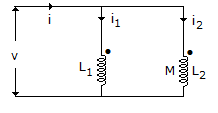
  3. The parallel RLC circuit shown in figure is in resonance. If

  4. A.
    IR < 1 mA
    B.
    | IR + IL | > 1 mA
    C.
    | IR + IL | < 1 mA
    D.
    | IL + IC | > 1 mA

  5. An ideal voltage source can not be converted into an equivalent current source.

  6. A.
    True
    B.
    False

  7. Load ZL for maximum power transfer is

  8. A.
    R
    B.
    R + jωL
    C.
    R - jωL
    D.
    none

  9. Eddy current loss is proportional to

  10. A.
    f and B2m
    B.
    f2 and B2m
    C.
    f2 and Bm
    D.
    f and Bm

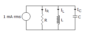
  11. Which is correct for a driving point function?

  12. A.
    If the real part of a pole or zero is zero, that pole must be simple
    B.
    If the real part of a pole or zero is zero, that pole or zero must be simple
    C.
    If the real part of a zero is zero, that pole or zero must be simple
    D.
    If the real part of a zero is zero that zero must be simple

  13. In the circuit, the value of the voltage source E is

  14. A.
    -22 V
    B.
    -12 V
    C.
    +12 V
    D.
    -10 V

  15. The r.m.s. value of a half-wave rectified current is 100 A. Its value for full-wave rectification would be __________ amperes.

  16. A.
    141.4
    B.
    200
    C.
    200/p
    D.
    40/p

  17. For the circuit of figure


  18. The sum of positive real function is positive real.

  19. A.
    True
    B.
    False