ECE :: Exam Questions Paper
-
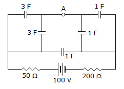
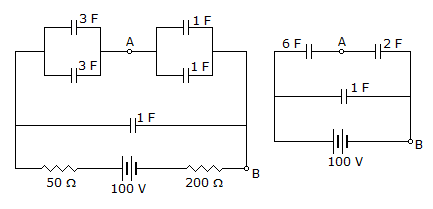
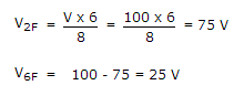
Determine the potential difference between the points A and B in the steady state
-
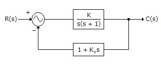
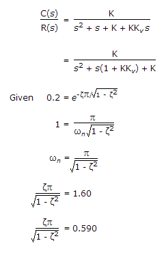
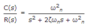
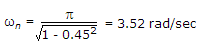
Find the value of K and velocity constant Kv so that the maximum overshoot in the unit step response is 0.2 and the peak time is 1 sec.
-
The transfer function of a discrete time LTI system is given by
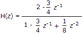
Consider the following statements:
S1: The system is stable and causal for ROC: |z| > 1/2
S2: The system is stable but not causal for ROC: |z| < 1/4
S3: The system is neither stable nor causal for ROC: 1/4 < |z| < 1/2
Which one of the following statements is valid? -
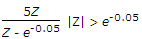
In the following network, the switch is closed at t = 0- and the sampling starts from t = 0. The sampling frequency is 10Hz.
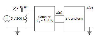
The expression and the region of convergence of the z-transform of the sampled signal are -
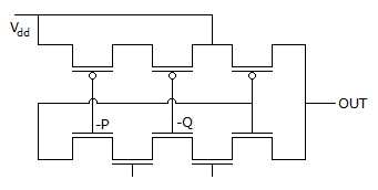
The logic function implemented by the following circuit at the terminal OUT is
-
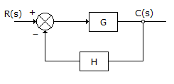
Consider a control system shown in given figure. For slight variation in G, the ratio of open loop sensitivity to closed loop sensitivity will be given by
-
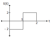
Consider the signal S(t) shown below :

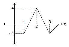
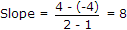
The slope of the matched filter output during the interval -
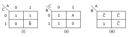
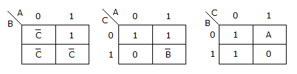
The logic function f(A B, C) = Σm(0, 2, 4, 5, 6) represented by
-
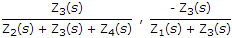
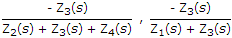
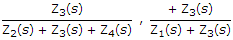
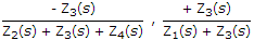
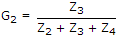
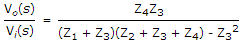
An electrical system and its signal-flow graph representation are shown in figure (a) and (b) respectively
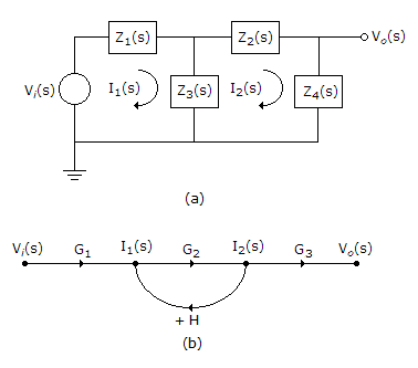
The values of G2 and H, respectively are -
Consider the circuit shown below of 2 : 1 MUX is given by the function g = ac + bc
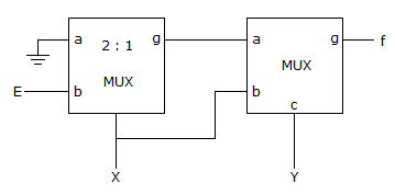
Then f is

 Whatsapp
 Facebook


 |z| < e-5
  |z| < e-0.05
  |z| < e-0.05
  |z| > e-5
  5.e-0.05n.Z-n
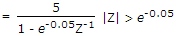
 .
.
 .
.


 ...(iii)
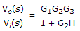 From SFG ...(iv)
 X
X