GATE 2017-2018 :: GATE EEE
- A dielectric slab with 500 mm × 500 mm cross-section is 0.4 m long. The slab is subjected to a uniform electric field of E = 6ax + 8ay kV/mm. The relative permitivity of the dielectric material is equal to 2. The value of constant εo is 8.85 * 10-12 F/m. The energy stored in the dielectric in Joules is
-
A matrix has eigenvalues “1 and “2. The corresponding eigenvectors are
 and
and  respectively. The matrix is
 -
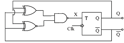
The clock frequency applied to the digital circuit shown in the figure below is 1 kHz. If the initial state of the output Q of the flip-flop is '0', then the frequency of the output waveform Q in kHz is
-
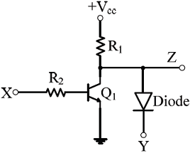
In the circuit shown below, Q1 has negligible collector-to-emitter saturation voltage and the diode drops negligible voltage across it under forward bias. If Vcc is +5 V, X and Y are digital signals with 0 V as logic 0 and Vcc as logic 1, then the Boolean expression for Z is
- Two magnetically uncoupled inductive coils have Q factors q1 and q2 at the chosen operating frequency. Their respective resistances are R1 and R2. When connected in series, their effective Q factor at the same operating frequency is
-
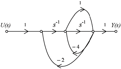
The signal flow graph for a system is given below. The transfer function Y(s)/U(s) for this system is
-
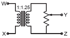
The following arrangement consists of an ideal transformer and an attenuator which attenuates by a factor of 0.8. An ac voltage VWX1 = 100V is applied across WX to get an open circuit voltage VYZ1 across YZ. Next, an ac voltage VYZ2 = 100V is applied across YZ to get an open circuit voltage VWX2 across WX. Then, VYZ1/VWX1, VWX2/VYZ2 are respectively,
-
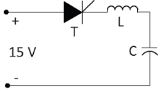
Thyristor T in the figure below is initially off and is triggered with a single pulse of width 10 μs. It is given that L = (100/π)μ H and C = (100/π)μ F Assuming latching and holding currents of the thyristor are both zero and the initial charge on C is zero, T conducts for
- A 4-pole induction motor, supplied by a slightly unbalanced three-phase 50 Hz source, is rotating at 1440 rpm. The electrical frequency in Hz of the induced negative sequence current in the rotor is

 Whatsapp
 Facebook


 .
. .
. .
. .
. .
. .
. .
.