GATE 2017-2018 :: GATE ECE
-
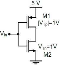
In the CMOS circuit shown, electron and hole mobilities are equal, and M1 and M2 are equally sized. The device M1 is in the linear region if
- A binary symmetric channel (BSC) has a transition probability of 1/8. If the binary transmit symbol X is such that P(X=0) = 9/10, then the probability of error for an optimum receiver will be
-
The signal m(t) as shown is applied both to a phase modulator (with kp as the phase constant) and a frequency modulator (with kf as the frequency constant) having the same carrier frequency.
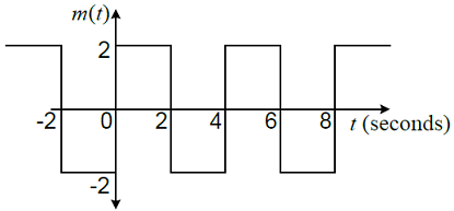 The ratio kp/kf (in rad/Hz) for the same maximum phase deviation is
 -
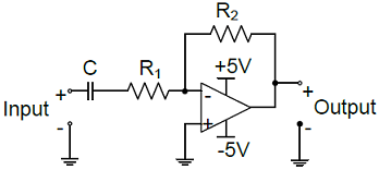
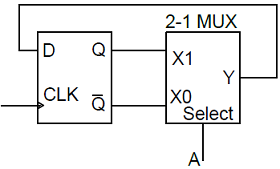
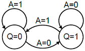
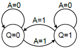
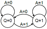
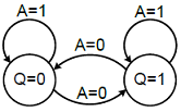
The circuit shown is a
-
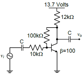
The voltage gain Av of the circuit shown below is
-
Given that A =
 and I =
  the value of A3 is
 -
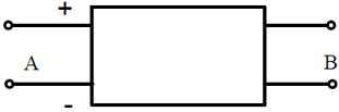
With 10 V dc connected at port A in the linear nonreciprocal two-port network shown below, the following were observed: (i) 1 Ω connected at port B draws a current of 3 A(ii) 2.5 Ω connected at port B draws a current of 2 AWith 10 V dc connected at port A, the current drawn by 7 Ω connected at port B is
-
With 10 V dc connected at port A in the linear nonreciprocal two-port network shown below, the following were observed: (i) 1 Ω connected at port B draws a current of 3 A(ii) 2.5 Ω connected at port B draws a current of 2 AFor the same network, with 6 V dc connected at port A, 1 Ω connected at port B draws 7/3 A. If 8 V dc is connected to port A, the open circuit voltage at port B is

 Whatsapp
 Facebook


 .
. .
. .
. .
.