Home / ECE / Power Electronics :: Section 8

ECE :: Power Electronics

  1. In a 3 phase bridge inverter, the gating signals for the three phases have a phase difference of

  2. A.
    120°
    B.
    60°
    C.
    240°
    D.
    any of the above

  3. Assertion (A): The circuit of figure thyristor will conduct for 180° during positive half cycle if it is continuously fired.

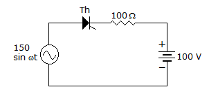
    Reason (R): A thyristor can conduct only when it is forward biased.

  4. A.
    Both A and R are correct and R is correct explanation of A
    B.
    Both A and R correct but R is not correct explanation of A
    C.
    A is correct but R is wrong
    D.
    A is wrong but R is correct

  5. The total number of leads in SCR, DIAC and TRIAC respectively are

  6. A.
    3, 2, 3
    B.
    2, 3, 3
    C.
    3, 3, 2
    D.
    3, 2, 4

  7. A single phase semiconverter is feeding a highly inductive load and has a freewheeling diode across the load. The waveshape of input current is

  8. A.
    sinusoidal
    B.
    rectangular
    C.
    sinusoidal or rectangular
    D.
    triangular

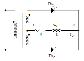
  9. In the below figure, the load is highly inductive. The firing angle is a for each of the thyristors. The periods of conduction of Th1 and Th2 respectively are

  10. A.
    0 to p and p to 2p
    B.
    a to p and p + a to 2p
    C.
    a to p + a and p + p to 2p + a
    D.
    a to p - a and p + a to 2p - a

  11. A crowbar circuit is generally needed for protection under fault conditions.

  12. A.
    True
    B.
    False

  13. Forward rating of an SCR is

  14. A.
    the maximum rate of rise of anode voltage which will trigger the SCR
    B.
    the maximum rate of rise of anode voltage which will not trigger the SCR if gate signal is applied
    C.
    the maximum rate of rise of anode voltage which will not trigger the SCR if gate signal is not applied
    D.
    either (b) or (c)

  15. The number of leads in a DIAC are

  16. A.
    2
    B.
    3
    C.
    4
    D.
    6

  17. The condition for underdamped oscillations in a series RLC circuit is


  18. The method of triggering SCS is

  19. A.
    application of positive pulse at cathode gate or negative pulse at anode gate
    B.
    application of pulse at anode gate
    C.
    application of pulse at cathode gate
    D.
    application of low voltage at anode