ECE :: Measurements and Instrumentation
-
A piezoelectric force transducer has a charge sensitivity of 20 pC/N. It is connected to a charge amplifier and overall gain of transducer and amplifier is 50 mV/N. The gain of amplifier is
-
An LVDT is used to measure displacement. The LVDT feeds a Voltmeter of 0-5 V range through a 250 gain amplifier. For a displacement 0.5 mm the output of LVDT is 2 mV. The sensitivity of instrument is
-
Assertion (A): When a wattmeter is used for low impedance loads, the pressure coil is connected across the load.
Reason (R): A wattmeter measures apparent power.
-
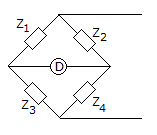
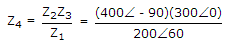
In figure, Z1 = 200∠60° Ω, Z2 = 400∠ - 90° Ω, Z3 = 300∠0°. Then Z4 for bridge to be balanced is
-
In a ballistic galvanometer, a charge of 100 μC gives a first swing of 25°. The charge required to cause first swing of 50° is
-
Two resistors R1 = 36 Ω ± 5% and R2 = 75 Ω ± 5% are connected in series. The total resistance is
-
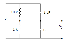
Figure shows an RC potentiometer to measure ac voltage. It is desired that V0/Vi should be independent of frequency. The value of C should be
-
In a strain measuring device using a strain gauge, the output quantity is
-
The Lissajous pattern observed on screen of CRO is a straight line inclined at 45° to x axis. If X-plate input is 2 sin ωt, the Y-plate input is

 Whatsapp
 Facebook


 .
. .
.
 .
.