ECE :: Network Analysis and Synthesis
-
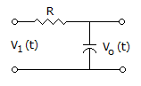
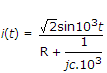
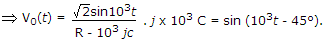
For the circuit shown in the figure, the time constant RC = 1 ms. The input voltage is V1(t) = 2 sin 103 t. The output voltage V0(t) is equal to
-
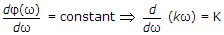
A low-pass filter frequency responce H (jω) = A (ω) ejΦ(ω) does not produce any phase distortion, if
-
In a tungsten filament lamp
-
An RLC series circuit has R = 8 Ω, XL = 8 Ω and XC = 8 Ω Its impedance is
-
Two similar mutually coupled coils have a total inductance of 900 mH and coefficient of coupling 0.5. The self inductance of each coils is
-
The function of a choke in a fluorescent lamp is
-
A series resonant circuit is fed by a voltage having rms value V. At resonance, the voltage across inductance VL and voltage across capacitance VC are related as
-
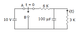
Calculate i(t) for t ≥ 0, assuming the switch has been in position A for a long time at t = 0, the switch is moved to position B.

 Whatsapp
 Facebook


 .
.|
A.
the current at the instant of switching is less than operating current
|
|
B.
the current at the instant of switching is more than operating current
|
|
C.
the current at the instant of switching is equal to operating current
|
|
D.
the current at the instant of switching may be less than or equal to operating current
|


 = 1.11 mA,