ECE :: Network Analysis and Synthesis
-
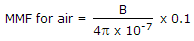
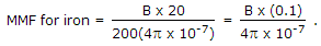
A magnetic circuit has an iron length of 20 cm and air gap length 0.1 cm. If μr = 200 then
-
A circuit is fed by two sources of the same frequency and values 100 ∠0° V and 20 ∠30°V. The current in a particular branch is 5 ∠19° A. If the magnitudes of the sources and changed to 200 ∠0° V and 40 ∠30° V, the current in that branch should be
-
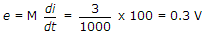
Two coils X and Y have self inductances of 5 mH and 10 mH and mutual inductance of 3 mH. If the current in coils X change at a steady rate of 100 A/s, the emf induced in coil Y is
-
Two capacitors of 2 μF and 4 μF capacitance are connected in series across a 30 V dc battery. After the capacitors have been charged, the voltage across them will be
-
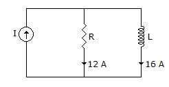
In the circuit shown in the figure, the current supplied by the sinusoidal current source I is
-
The frame of an electric motor is earthed through three earthing plates resistances 30 Ω, 20 Ω and 10 Ω respectively. During fault the energy dissipated by three plates are W1, W2 and W3. Then
-
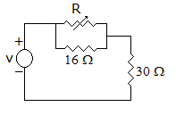
If figure, power dissipated in 30Ω resistance will be maximum when value of R =
-
Two voltages are 50 ∠0 V and 75 ∠ - 60° V. The sum of these voltages is
-
An RLC series circuit is fed form 100 V ac supply. Inductance is 1 H and Q = 7.5. At resonance, the voltage across inductance is

 Whatsapp
 Facebook


 and power dissipated =
  watts, which is the maximum possible value.