GATE 2017-2018 :: GATE Instrumentation
-
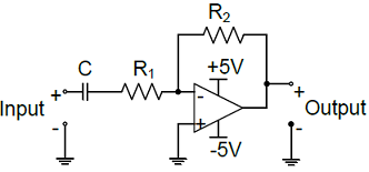
The voltage gain Av of the circuit shown below is

-
The state variable description of an LTI system is given by
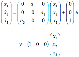 where y is the output and u is the input. The system is controllable for
 - The Fourier transform of a signal h(t) is H(jw) = (2 cosw)(sin 2w)/w. The value of h(0) is
-
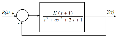
The feedback system shown below oscillates at 2 rad/s when
-
The circuit shown is a
-
The input x(t) and output y(t) of a system are related as y(t) =
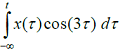 . The system is
 - The open loop transfer function of a unity negative feedback control system is given by G(s) = 150/[s(s + 9)(s + 25)]. The gain margin of the system is
- Water (density: 1000 kgm“3) stored in a cylindrical drum of diameter 1 m is emptied through a horizontal pipe of diameter 0.05 m. A pitot-static tube is placed inside the pipe facing the flow. At the time when the difference between the stagnation and static pressures measured by the pitotstatic tube is 10 kPa, the rate of reduction in water level in the drum is,
- A U-tube manometer of tube diameter D is filled with a liquid of zero viscosity. If the volume of the liquid filled is V, the natural frequency of oscillations in the liquid level about its mean position, due to small perturbations, is

 Whatsapp
 Facebook


 .
. .
. .
. .
.