Discussion :: Exam Questions Paper
-
Figure shows four D type FFs are connected as a shift register using an XOR gate. The initial state and 3 subsequent states for 3 clock pulses are also given
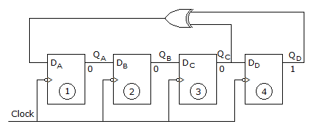
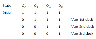
The state QA QB QC QD after the 4th clock pulse is

 Whatsapp
 Facebook


Answer : Option D
Explanation :
After the 3rd pulse FF3 is 0 and FF4 is 1, so that XOR output is 1 which is fed to DA.
So, QA = 1, QA to QB → 0
AB to AC → 0, QC → QD → 0.
Be The First To Comment