Discussion :: Digital Electronics
-
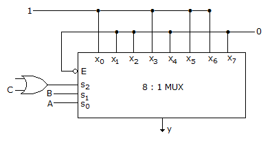
In the TTL circuit in the figure, S2 to S0 are select lines and X7 to X0 are input lines. S0 and X0 are LSBs. The output Y is

 Whatsapp
 Facebook


Answer : Option B
Explanation :
The MUX is made up of TTL circuit. For TTL circuit open terminal is taken high, since S2 select line is connected to OR gate whose one terminal connected to C and the other is open (high) so OR gate output is S2 = 1 + C = 1.
S2 = 1 S1(B) S0(A) Y 1 0 0 0 1 0 1 1 1 1 0 1 1 1 1 0
Y = S0⊕S1 => A⊕B.
Be The First To Comment