ECE :: Network Analysis and Synthesis
-
A current 10 sin (200t) A flows through a 5 mH inductance. The expression for voltage is
-
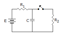
In figure, capacitor is used to develop pulses of short duration and large duty cycle across R2 when switch is closed. Which of the following combinations is best suited?
-
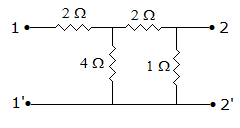
In figure, which value of ZL will cause maximum power to be transferred to the load?

-
A wave trap is a
-
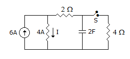
In following circuit, steady state is reached with S open, S is closed at t = 0, the current I at t = 0+ is given by
-
In an ac series RLC circuit the maximum phase difference between any two voltages can be
-
In a series circuit with XL constant and R variable the current locus lies in the third quadrant.
-
One coulomb charge is equal to the charge on
-
The internal impedance of a source is 3 + j 4 Ω. It is desired to supply maximum power to a resistive load. The load resistance should be

 Whatsapp
 Facebook


 = 1∠90° and V = IXL
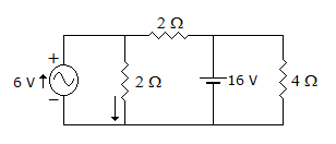
 24 volt.
  I = 16/2