ECE :: Network Analysis and Synthesis
-
If Va0, Va1, Va2 are sequence components of Va and Ia0, Ia1, Ia2 are sequence components of Ia, then total 3 phase power P is given by
-
Two capacitors of 1 μF and 2 μF are connected in series across a 10 V dc battery. After the capacitors have been charged, the charges across the two capacitors will be
-
A series RLC circuit has Q = 5. A voltage of 10 V rms is applied to it. At resonance, the voltage across C is
-
The pole of a reactive function
-
Wave A starts its positive half cycle at ωt = 30° and wave B starts its positive half cycle at ωt = 75° then wave B is leading wave A by 45°.
-
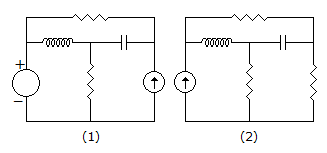
Assertion (A): For networks in figure (1) and (2) sum of products of branch voltages and branch currents at any time is zero.
Reason (R): The networks in figure (1) and (2) are not the same structurally.
-
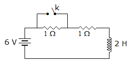
In the circuit of figure the switch is open for a long time, At t = 0 the switch is closed. At t = 0+ the current supplied by battery is
-
Assertion (A): The Laplace transform of a ramp is 1/s2.
Reason (R): The integral of a unit step function gives an impulse function.
-
An RL series circuit is initially relaxed. A step voltage E is applied. If t is time constant, voltage across R and L will be equal at t =

 Whatsapp
 Facebook


 .
.


