Home / ECE / Network Analysis and Synthesis :: Section 4

ECE :: Network Analysis and Synthesis

  1. An RL series circuit has an impedance of 20 Ω when frequency is 25 Hz. At f= 50 Hz, the impedance will be

  2. A.
    40 Ω
    B.
    20 Ω
    C.
    less than 40 W but more than 20 Ω
    D.
    less than 20 W but more than 10 Ω

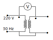
  3. In figure, the voltmeter is ideal. The transformer has two identical windings with perfect coupling. The reading of voltmeter is

  4. A.
    440 V
    B.
    220 V
    C.
    110 V
    D.
    zero

  5. The final value of is

  6. A.
    B.
    2
    C.
    1
    D.
    zero

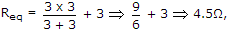
  7. The resistance of the circuit shown is figure is

  8. A.
    5 Ω
    B.
    More than 6 Ω
    C.
    More than 4 Ω
    D.
    Between 6 and 7 Ω

  9. The self inductances of two coils are 27 H and 3 H. If the winding or coils is such that 50% of flux of one links the other, the mutual inductance is

  10. A.
    30 H
    B.
    24 H
    C.
    9 H
    D.
    4.5 H

  11. In a lead acid cell, the positive plate has spongy lead.

  12. A.
    True
    B.
    False

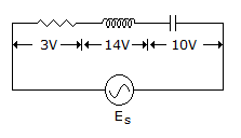
  13. The rms voltage measured across each of the circuit element in figure is as shown, when the circuit is excited by a sinusoidal voltage Es, the rms value of the source voltage es is

  14. A.
    10 volt
    B.
    2 volt
    C.
    Es
    D.
    5 volt

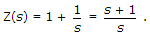
  15. For H(s) to be positive real, the condition Re[H(jω)] ≥ 0 for 0 ≤ ω ≤ ∞ is

  16. A.
    a necessary condition
    B.
    a sufficient condition
    C.
    a necessary and sufficient condition
    D.
    is not a necessary condition

  17. In the circuit, shown the current I marked is given by

  18. A.
    2.22 A
    B.
    1.78 A
    C.
    4.44 A
    D.
    2 A

  19. For a network having 1 Ω resistor and 1 F capacitor in series Z(s) =

  20. A.
    B.
    C.
    1 + s
    D.