Discussion :: Network Analysis and Synthesis
-
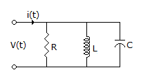
The circuit shown in the figure, with R = 1/3 Ω, L = 1/4H, C = 3F has input voltage v(t) = sin2t. The resulting current i(t) is

 Whatsapp
 Facebook


Answer : Option A
Explanation :
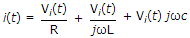
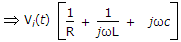
i(t) = iR(t) + iL(t) + iC(t)
 .
.
Be The First To Comment