Discussion :: Network Analysis and Synthesis
-
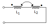
The equivalent inductance measured between the terminals 1 and 2 for the circuit shown in the figure is

 Whatsapp
 Facebook


Answer : Option D
Explanation :
L = L1 + L2 - 2M because currents are opposing.
Be The First To Comment