Discussion :: Exam Questions Paper
-
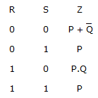
For the circuit shown in the following figure I0-I3 are inputs to the 4:1 multiplexer R(MSB) and S are control bits
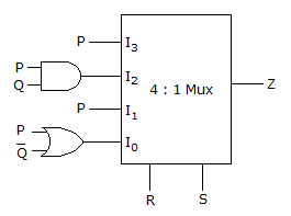
The output Z can be represented by
|
A.
PQ + PQ S + Q R S
|
|
B.
P Q + PQ R + P Q S
|
|
C.
P Q R + P QR + PQRS + Q R S
|
|
D.
PQ R + PQR S + P Q R S + Q R S
|

 Whatsapp
 Facebook


Answer : Option B
Explanation :
Use this to find solution
Be The First To Comment